Overview
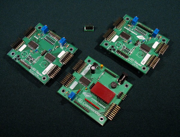 The LED Commander System is a modular control system for LED circuits. It is applicable to conventional LEDs with a forward voltage drop between 0.7Vdc and 5.0Vdc. Their forward current should be in the 10mA to 40mA range. The system is comprised of three basic electronic boards: the LED Commander or the Serial LED Cmdr and the LED Squad. Applications include:
- Custom signs with LED outlines, graphics or action
- LED highlights or action in relief maps
- An alternative to expensive fiber optic illumination in complex lighting sequenced displays
Click on any image above right for a closer view.
LED Commander
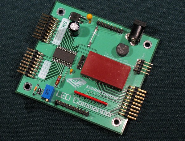 The LED Commander Board provides the logic controller and the first 16 LED circuits’ outputs. It has a total of 13 available IOs. Four IOs are only available to control more LED circuits. That leaves nine IOs which can either be used to control other LED circuits or as outputs to external devices (relay drivers, control signals, etc) or triggers from other devices (buttons, other system controllers, etc). Each IO can provide control for 16 additional LED circuits. Click on image above right for a closer view.
Each LED output port (LED circuit) has two pins: one for the LED anode and one for the cathode. If LEDs are in series one pin goes to the first LED’s anode and the other to the last LED’s cathode. Please note there is no requirement for a current limit resistor. A maximum of 14 IOs can be used for LED circuit control; each controlling 16 LED circuits. That amounts to 224 individual LED circuits that can be controlled with one system. Each LED circuit could have as many as 6 LEDs in series, which totals 1,344 LEDs for each system. If all, or many, of the LED circuits are to react in unison (i.e., replicate each other), only real estate and power supply current limit the total number of LEDs controlled by one system. That limit should be well over 2,500. If more LED circuits are required, LED Commander systems can be daisy-chained together. If an IO is used as an input, the input should be dry contact closure to ground or a TTL signal. If it is used as an output, it will be a TTL level: zero or one.
The LED Commander can use any reputable, commercial power supply or wall wart. The voltage can be between 7.5Vdc and 16Vdc. The larger voltage power supplies, however, should only be used with systems that either have multiple LEDs in each circuit or result in very low ‘on’ duty cycle. Otherwise the voltage should be between 7.5Vdc and 9Vdc; the lower the better. You should provide a power supply capable of a total current equal to the number of LED circuits multiplied by 40mA. We can configure a system for a distributed (multiple) power supply system as discussed with the LED Squad Boards.
Here are two short videos that demonstrate the LED Commander. The first demo has 128 individual LED circuits and shows each of our standard probrams: blink, LED chase, inverse LED chase and a growing tail (bar graph). The second shows a scintillate program. Please be aware that LED placement can greatly improve the visual affect, but our demo board is limited to side-by-side LEDs for each Squad Board.
Basic LED Commander Demo
Scintillate Demo
Squad Board
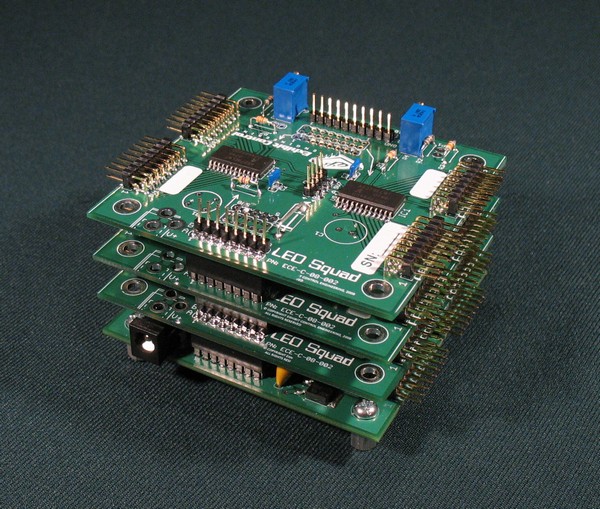
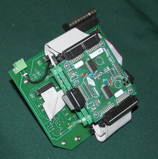
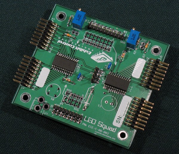 The LED Squad Board provides the capability to add LED circuits to systems, as required. Each board adds 32 LED circuits to the system. The Squad boards must be individually configured for the system they are being designed into. The first configuration issue is whether it is a Squad ‘A’ card or a Squad ‘B’ card. The system is designed so the Squad boardsplug in piggyback style on the LED Commander. Squad ‘A’ cards plug into either a Commander board or a Squad ‘B’ board. The Squad ‘B’ boardsonly plug in on top of a Squad ‘A’ board.
 The LED Squad board gets its logic power from the LED Commander board. However, it can be configured to supply its own LED power that can then be distributed downstream to other Squad Boards, thus providing a means for distributed power rather than a single power supply. Please note, there is no redundancy in this arrangement. The same power supply guidance discussed earlier applies.
Unusual Application of a LED Commander
 We did not envision the following application for the LED Cmdr when we developed it, but we ended up using it as a proposal for a quick turn solution to the following requirement. The requirement was for an exhibit that needed an alphanumeric display that did the following:
- Had four each two-inch tall alphanumeric characters
- Could display the following messages: four dashes, the word “STOP”, the word “GO”, and provide a countdown from thirty seconds, in one second increments.
- Could adjust the countdown plus or minus 15 seconds
- Could have the firmware updated in the field
- Take a button input from the visitor
- Control the illumination of the visitor button
- Needed to trigger five digital message repeater (DMR) audio files via TTL signals
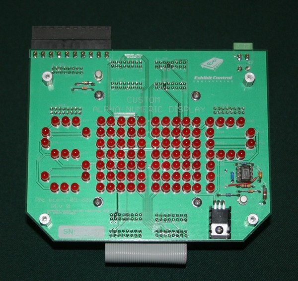
 The fact that we could not find a two-inch, 15-bar segment LED in the electronic component market swayed us to design a custom LED circuit board that the LED Commander could be mounted on and provide all of the specifications. It should be noted that this LED Commander is controlling 80 individual LED circuits in addition to meeting the other requirements listed above. Click on the images to see a closer view of our solution.
Click on the link below to see a video of the operation. You will note in the video some of the characters seem more blurred than others. We were experimenting with heat shrink tubing on the LEDs to reduce radiant light patterns being reflected by adjoining LEDs.
Sample LED Cmdr Application Video
Serial LED Commander
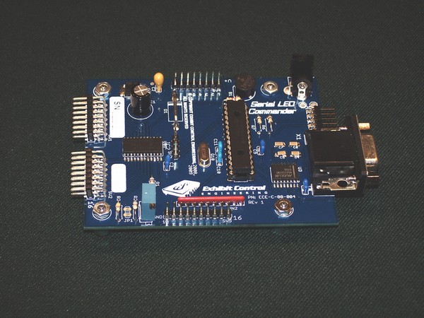 Unlike the LED Cmdr, this version is not a stand-alone device. Rather, it controls its LED Squad boards based on five-byte RS232 strings it receives from another device, such as PC or control system. Since it uses two of its IOs for communication, the maximum number of LED circuits it can control is 192. Other differences from the LED Cmdr include: no programming requirement and no other inputs for the device except the serial communication. The serial protocol is 2400 baud, eight bits, no parity and 1 stop bit. The unit responds after accomplishing each command. The LED Squad boards attach piggyback, as with the LED Cmdr. Power supply considerations are the same as the LED Cmdr.
Another Application for Serial LED Cmdr: Having said all that, we recently had a client who not only wanted synchronized LEDs in their exhibit, they also wanted audio to play on cue from a digital message repeater (DMR). Because they had quite a number of messages to play, there weren’t enough IOs to do everything that needed to be done. So we used the Serial LED Cmdr to not only control the LEDs but also send RS232 strings to the DMR to play specific audio messages in the time line. This suggested that maybe there are a lot of other applications for the Serial LED Commander; i.e. start a video during or after the start of the LED sequence or control any other RS232 controllable device. Got an idea? Contact us
One of Our More Demanding Applications: World Map in the University of Alabama – Huntsville Campus Student Union
The University wanted a 16-foot by 8-foot map the world approximately nine feet of the floor in their Student Union. They wanted it to depict which world countries had students in attendance at the University and which countries has visiting UAH students. They wanted two LEDs in each country: a blue one for countries with foreign students in attendance and a white one for countries with UAH students. We used two Serial Commanders, each controlling 194 LEDs for a total of 388 LEDs. We also provided a Windows PC program for the University staff to update the LED Cmdrs with the current information that was loaded into non-volatile RAM. The program provided two check boxes for each country, one for each LED. They simply check the correct boxes and loaded the data through a serial port in a nearby closet. The program also had easy maintenance provisions for checking all LED operations and saving configurations for future use. See the illustration below of a screen shot of the program.

Below are some photos of the final installation.

Visitor View of Map
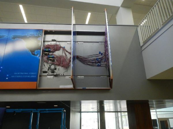
Behind the Scenes

One LED Cmdr System (194 LED)
An Example of an Animated LED Show
Other Configurations
There are other minor options in configuration that may be applicable in your system. If you provide us the technical approach and ‘story line, we will advise you of the LED Commander’s ability to achieve it and the best configuration.
Programming
If you can use one of our demo programs, we will provide that at no charge. Our demo programs include a blink on, blink off; a LED chase (one LED illuminated at a time chasing from one end to the other); inverse chase, all on except a single off LED that moves down the line, and a growing tail or bar graph effect. We just recently added another demo program to our list: a scintillating effect (very rapid, random, on-off of individual LEDs – like a sparkler). Although we cannot provide a shopping list cost for programming, you can expect programming cost to start at $100 that will cover up to 100 single LED state changes and then $0.40 per state change after that. This assumes simple start and stop controls. More elaborate schemes or on-site programming (to accurately synchronize LED sequences with audio, video or show events) can be quoted on a case-by-case basis.
Other Considerations
Because the specifics of applications for the LED Commander can be so diverse, we do not provide the following: power supplies, LEDs, LED wiring or connectors or mounting hardware (other than the card stacking arrangement inherent in the Commander’s design). We can supply you information on what and where to obtain the installation materials you might need.
Pricing
- LED Commander Board $300
- Serial Commander Board $375
- LED Squad Board (A or B) $ 50
- LED Group Connector Call
Programming
- Demo Programs – No Charge
- Initial Program (first 100 transitions) $100
- Each Additional Transition $0.40